



MBBR Design & Calculation Guide | How to Size a Moving Bed Biofilm Reactor
Sizing an MBBR system correctly determines whether your plant meets discharge standards on day one - or struggles to catch up for years. This guide walks through the full MBBR design calculation sequence: from influent characterization to carrier volume, aeration demand, and hydraulic retention time. All formulas are presented with worked examples based on a typical industrial wastewater scenario.
If you need carrier media to match your calculated specifications, view Juntai's full MBBR carrier range or contact our engineering team for project-specific sizing support.
Step 1 - Characterize Your Influent
Every MBBR design begins with a reliable influent characterization. The minimum dataset required for sizing includes:
| Parameter | Typical Range | Design Notes |
| Flow rate (Q) | m³/day or m³/h | Use peak daily flow, not average |
| BOD₅ (influent) | 150–5,000 mg/L | Soluble BOD preferred for MBBR sizing |
| COD (influent) | 300–10,000 mg/L | BOD/COD ratio indicates biodegradability |
| NH₄-N (influent) | 20–200 mg/L | Critical for nitrification stage sizing |
| TN, TP | mg/L | Required for nutrient removal stages |
| TSS (influent) | mg/L | Pre-screening recommended if TSS > 200 mg/L |
| Water temperature (T) | °C (min/max/average) | Use minimum temperature for conservative design |
| pH range | 6.5–8.5 optimal | pH < 6.5 or > 9.0 inhibits nitrification |
Step 2 - Calculate BOD Surface Load (SALR)
The Surface Area Loading Rate (SALR) is the core parameter that governs MBBR reactor sizing. It expresses how much BOD load (grams) is applied per square meter of biofilm carrier surface area per day.
Formula:
SALR (g BOD/m²·day) = [Q (m³/day) × BOD_influent (mg/L)] / [A_effective (m²) × 1000]
Where A_effective is the total protected surface area of the carrier media inside the reactor.
Typical SALR design values:
| Application | Design SALR |
| BOD removal (municipal) | 5–10 g BOD/m²·day |
| BOD removal (industrial, high-load) | 10–25 g BOD/m²·day |
| Nitrification only | 0.5–1.5 g NH₄-N/m²·day |
| Combined BOD + nitrification | 3–6 g BOD/m²·day |
Step 3 - Calculate Required Carrier Surface Area
Rearranging the SALR formula to find the required carrier surface area:
A_required (m²) = [Q (m³/day) × BOD_removed (mg/L)] / [SALR (g/m²·day) × 1000]
Where BOD_removed = BOD_influent − BOD_effluent (target)
Worked Example:
Flow: 500 m³/day | BOD influent: 300 mg/L | BOD effluent target: 30 mg/L | Design SALR: 7 g/m²·day
A_required = (500 × 270) / (7 × 1000) = 135,000 / 7,000 = 19,286 m²
Step 4 - Calculate Carrier Volume Required
Once you know the required surface area, divide by the specific surface area (SSA) of your chosen carrier to get the volume of media needed:
V_carrier (m³) = A_required (m²) / SSA (m²/m³)
Specific Surface Area values for common Juntai MBBR carriers:
| Carrier Model | SSA (m²/m³) | Recommended Application |
| MBBR K1 | 500 | Municipal BOD removal, general applications |
| MBBR K3 | 500 | Nitrification, municipal STP |
| MBBR K5 | 800 | High-rate BOD removal, compact systems |
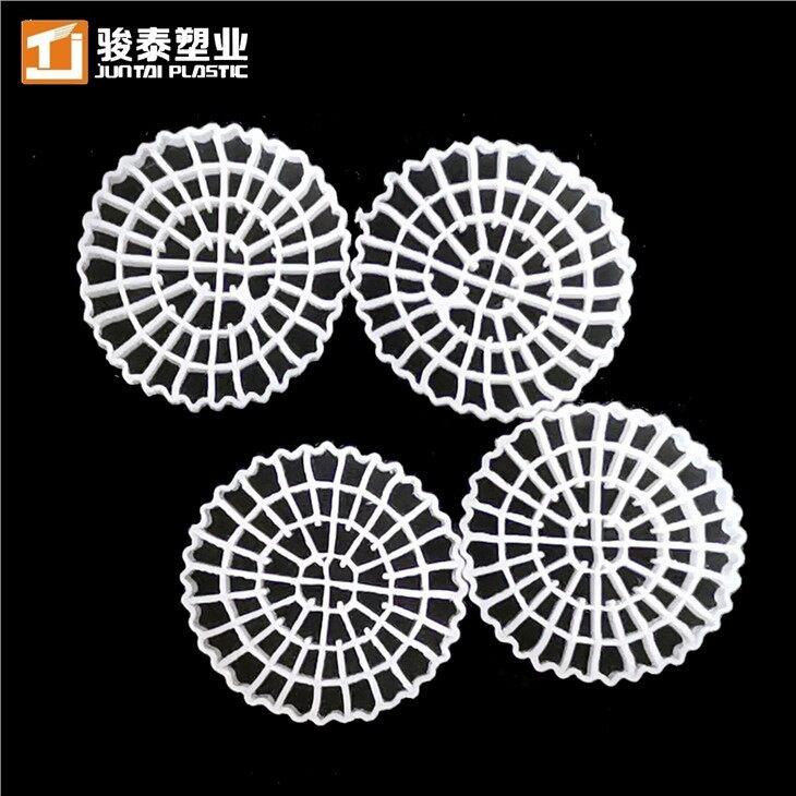
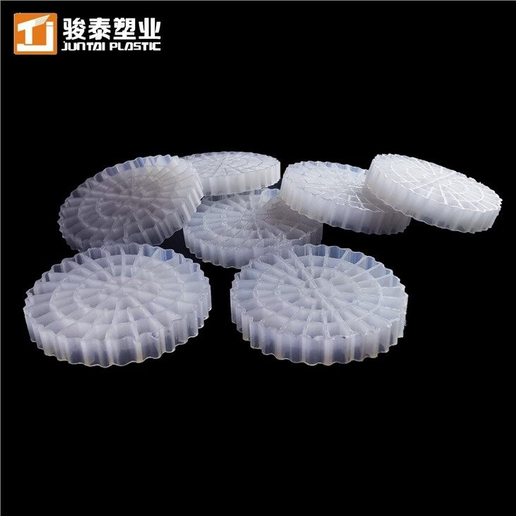
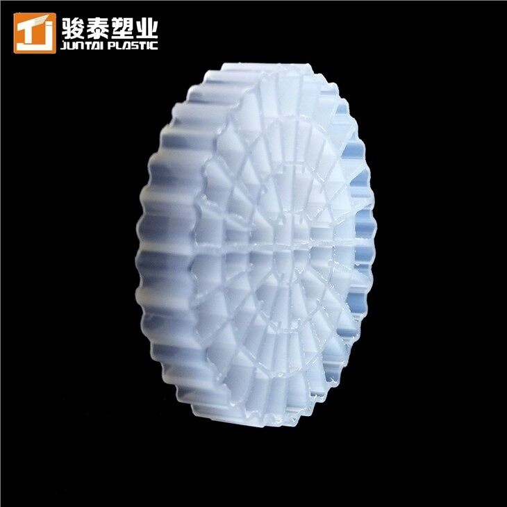
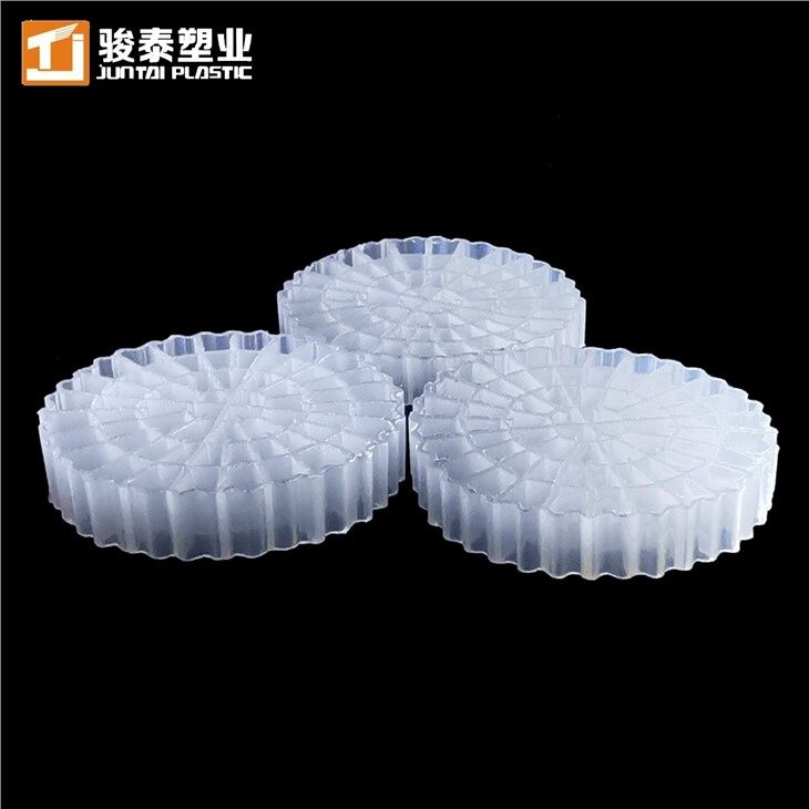
| juntai MBBR 19 25×12mm | >650 | Municipal STP, general BOD removal, cost-effective large-scale projects |
| juntai MBBR 37 25×12mm | >800 | Industrial high-TDS, pharmaceutical, chemical wastewater |
| juntai MBBR 04 11×7mm | >900 | Aquaculture RAS, compact reactors, high-load industrial nitrification |
| juntai MBBR 64 25×4mm | >1200 | Ultra-high-rate applications, space-critical retrofits, maximum surface area per m³ |
Continuing worked example (K5 carrier, SSA = 800 m²/m³):
V_carrier = 19,286 / 800 = 24.1 m³ of carrier media
Step 5 - Calculate Reactor Volume
The carrier fill ratio (fraction of reactor volume occupied by media) determines reactor size. Standard fill ratios range from 30% to 67%, with 50% being most common for BOD removal applications.
V_reactor (m³) = V_carrier (m³) / Fill Ratio
Fill ratio guidelines:
| Application | Recommended Fill Ratio |
| BOD removal | 40–50% |
| Nitrification | 50–67% |
| Denitrification | 40–50% |
| Maximum (any application) | 67% (do not exceed) |
Continuing worked example (fill ratio = 50%):
V_reactor = 24.1 / 0.50 = 48.2 m³
Step 6 - Verify Hydraulic Retention Time (HRT)
Check that the resulting HRT is within acceptable bounds for your application:
HRT (hours) = [V_reactor (m³) / Q (m³/h)]
Continuing worked example (Q = 500 m³/day = 20.8 m³/h):
HRT = 48.2 / 20.8 = 2.3 hours
Typical HRT ranges:
| Application | Typical HRT |
| BOD removal (municipal) | 1–3 hours |
| BOD removal (industrial) | 2–6 hours |
| Nitrification | 2–4 hours |
| Combined BOD + nitrification | 3–8 hours |
Step 7 - Aeration Demand Calculation
MBBR aeration must serve two functions simultaneously: keeping carriers in suspension (mixing) and supplying dissolved oxygen (DO) for biological activity. The governing oxygen demand is calculated as follows:
Oxygen demand for BOD removal:
O₂_BOD (kg O₂/day) = BOD_removed (kg/day) × 1.0
Oxygen demand for nitrification (if applicable):
O₂_NH₄ (kg O₂/day) = NH₄-N_removed (kg/day) × 4.57
Total oxygen demand:
O₂_total = O₂_BOD + O₂_NH₄
Aeration system sizing (standard air blower, α = 0.7, SOTE = 8%):
Air_required (m³/h) = O₂_total (kg/day) / (0.278 kg O₂/m³ air × α × SOTE × 24)
Minimum aeration for carrier suspension (independent of oxygen demand):
Maintain a minimum airflow of 0.3–0.5 Nm³/h per m² of reactor floor area, regardless of oxygen calculation. This ensures adequate carrier mixing at all times.
Step 8 - Temperature Correction
Biological reaction rates decrease significantly at lower temperatures. Apply the Arrhenius correction to adjust the design SALR for your minimum operating temperature:
SALR_T = SALR_20 × θ^(T−20)
Where θ = 1.047 (standard Arrhenius temperature coefficient for biofilm systems) and T = minimum design water temperature (°C).
| Temperature | Correction Factor vs. 20°C |
| 20°C | 1.00 (baseline) |
| 15°C | 0.79 |
| 12°C | 0.68 |
| 10°C | 0.62 |
| 8°C | 0.56 |
If your minimum water temperature is 12°C, multiply your required carrier surface area by 1/0.68 = 1.47× to maintain equivalent treatment performance.
Complete Design Summary - Worked Example
| Design Parameter | Value |
| Influent flow | 500 m³/day |
| BOD removal required | 300 → 30 mg/L (90%) |
| Design SALR | 7 g BOD/m²·day |
| Required carrier surface area | 19,286 m² |
| Carrier selected | MBBR K5 (SSA = 800 m²/m³) |
| Carrier volume required | 24.1 m³ |
| Fill ratio | 50% |
| Reactor volume | 48.2 m³ |
| Hydraulic retention time | 2.3 hours |
| Oxygen demand (BOD only) | 135 kg O₂/day |
Common Design Mistakes to Avoid
Using average flow instead of peak flow
MBBR systems must handle peak hydraulic and organic loads without performance loss. Always size for peak daily flow (typically 1.5–2× average for municipal systems, up to 3× for batch industrial operations). Under-designing for average conditions leads to effluent violations during peak periods.
Ignoring temperature correction
A system designed for 20°C water temperature will lose 30–40% of its treatment capacity at 10°C. Plants in cold climates that skip temperature correction routinely fail ammonia limits in winter. Use minimum annual water temperature as your design condition.
Exceeding 67% fill ratio
At fill ratios above 67%, carriers begin to pack and lose free movement. The biofilm activity advantage of the moving bed is lost, and the system effectively becomes a fixed-film reactor with poor oxygen transfer. Always verify mixing adequacy with a physical fill ratio test before commissioning.
Selecting carrier SSA without considering protected area
Total SSA and effective (protected) SSA are different values. In turbulent aerated reactors, only biofilm in protected internal channels contributes to stable long-term treatment. Carriers with high total SSA but minimal internal structure lose a disproportionate share of their biofilm under hydraulic shear.
Insufficient pre-treatment
MBBR carriers are not filters. Coarse solids (hair, fibres, large particles) accumulate in carrier channels and reduce effective surface area over time. Install bar screens (≤ 3 mm) and grit removal ahead of any MBBR reactor handling raw industrial or municipal wastewater.
Need Help with Your MBBR Calculation?
The formulas above cover standard BOD removal and nitrification scenarios. For more complex systems - combined nitrification/denitrification, IFAS configurations, high-salinity industrial wastewater, or multi-stage reactors - design calculations become significantly more involved.
Juntai's engineering team provides free MBBR sizing support for qualified projects. Send us your influent data and effluent targets, and we will return a recommended carrier type, volume, fill ratio, and reactor sizing within 24 hours.
Manufacturer: Hangzhou Juntai Plastic Products Co., Ltd.


| Item No. | MBBR 64 | |
|
Diameter* Height |
25 mm* 4mm |
|
|
Surface Area |
> 1200 m2/m3 |
|
|
Rooms |
64 rooms |
|
|
|
|


